How to use the Petros CH32H417M Alef board
Set up the Petros CH32H417M Alef as a Pico-sized RISC-V camera board.
Set up the Petros CH32H417M Alef as a Pico-sized RISC-V camera board.
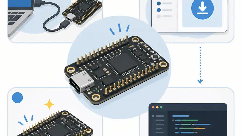
If you are building embedded camera hardware, this guide shows how to get the Petros CH32H417M Alef from unboxed board to a working development setup. You will end up with the board powered, wired for debug, matched with the OV2640 module, and ready for USB 3.0 camera firmware work.
This is written for developers who want a compact RISC-V platform with a camera interface, Pico-compatible headers, and a path toward USB Video Class experiments. The steps below focus on practical setup, not speculation, so you can move from hardware inspection to a host-visible test quickly.
Before you start
Get the latest AI news in your inbox
Weekly picks of model releases, tools, and deep dives — no spam, unsubscribe anytime.
No spam. Unsubscribe at any time.
- Petros CH32H417M Alef board
- Phos Ayin OV2640 2MP camera module
- USB 3.0 Type-A cable and a USB 3.0 host port
- Optional Amnos LinkE Alef debug board or another SWD/UART6 debugger
- Host computer with Windows, Linux, or macOS
- MounRiver SDK installed for WCH CH32H417 development
- RISC-V toolchain support if your SDK install does not bundle it
- Basic soldering or header-connection tools if your board arrives unassembled
Step 1: Inspect the board layout
Goal: confirm that the board matches the intended hardware path before you connect power or peripherals. The Petros CH32H417M Alef is Pico-sized, uses the WCH CH32H417M MCU, and exposes two 20-pin Pico-compatible headers plus a 6-pin SWD and UART6 debug header.
Check the silkscreen, connector orientation, and the camera interface area. The board also includes a USB 3.0 Type-A port for power, data, and flashing, so make sure you can identify that connector before plugging in a host cable.
Verification: you should be able to point to the USB 3.0 port, the camera connector, and the debug header without guessing.
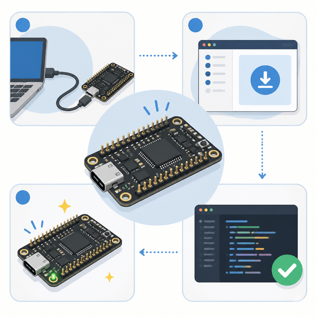
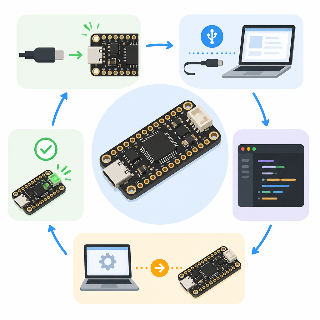
Step 2: Connect power and host USB
Goal: bring the board up safely and confirm that the power path is stable. The board can take 5V from the USB 3.0 port or from the pin header, and it uses a 3.3V/1A LDO for onboard logic.
1. Connect the USB 3.0 cable to a host port that can supply data and power.
2. Watch the power LED on the board.
3. If you need bench power later, feed 5V only through the documented power path.
4. Avoid attaching the camera or debug board until the board powers cleanly.
Verification: you should see the power LED light and the host should detect a newly attached USB device or at least enumerate a flashing-capable board.
Step 3: Attach the OV2640 camera module
Goal: create the camera hardware chain that the MCU expects for DVP capture. The Petros board uses a 40-pin B2B connector for the 2MP OV2640 camera module, and the MCU supports DVP plus SPI, I2C, and ADC interfaces around that camera path.
Seat the Phos Ayin OV2640 module carefully, then verify that the connector is fully engaged and aligned. If your bundle includes the camera module, this is the point where the board becomes a camera platform rather than just a USB 3.0 MCU board.
Verification: you should have a mechanically secure camera connection with no visible skew, and the module should not wobble when lightly touched.
Step 4: Wire the debugger and serial console
Goal: gain firmware upload and log access before you start modifying code. The board does not include an onboard Link-E debugger, so the SWD and UART6 header is your main path for development access.
Connect the Amnos LinkE Alef or a compatible debugger to the 6-pin header, then map SWD for flashing and UART6 for console output. Keep the wiring short and double-check the pin order against the vendor pinout before powering the debug adapter.
Verification: you should be able to connect from your IDE or debug tool and see the target MCU respond on SWD, with serial output available from UART6.
Step 5: Open the SDK camera sample
Goal: start from vendor code that already knows about DVP and USB 3.0. The WCH CH32H417 development SDK includes DVP and USB 3.0 code samples for the MounRiver SDK, and CNX Software noted a USB SS0 SuperSpeed UVC DVP sample that may be a useful starting point.
Clone or open the SDK project, then locate the sample that combines USB SuperSpeed and DVP capture. Adjust board-specific pin definitions, clock settings, and camera init code so they match the Petros hardware rather than the reference board.
git clone <your-wch-sdk-repo-url>
cd <sdk-root>
# Open the USB SS0 UVC DVP sample in MounRiver
# Update board pins, camera init, and USB descriptors for Petros
Verification: you should be able to build the sample without missing headers, and the firmware image should flash to the board from your IDE or command line tool.
Step 6: Test USB camera enumeration
Goal: confirm that the board behaves like a camera device on the host. The likely end state is a standard USB UVC webcam presentation, although the public documentation is still sparse and the camera demo may need firmware work first.
Flash the build, reconnect the board, and inspect the host device list. If the firmware is correct, the host should enumerate a USB Video Class device rather than only a generic USB peripheral. CNX Software also reported a USB 3.0 transfer test at 430 MB/s without the camera module, which gives you a performance target for the data path.
Verification: you should see a UVC-style camera entry on the host, or at minimum a recognized USB SuperSpeed device with the expected firmware behavior.
| Metric | Before/Baseline | After/Result |
|---|---|---|
| USB transfer rate | Not stated for a configured camera build | 430 MB/s in a USB 3.0 transfer test without the camera module |
| Board size | Typical dev board footprint | 52 mm × 21 mm Pico-sized board |
| Memory | Standard MCU-class SRAM/Flash | 896 KB SRAM and 960 KB Flash |
Common mistakes
- Using a USB 2.0 cable or port. Fix: move to a true USB 3.0 cable and host port so SuperSpeed enumeration and flashing work as expected.
- Skipping the debugger. Fix: add the SWD/UART6 adapter early, because the board has no onboard Link-E debugger.
- Assuming the camera sample is board-ready. Fix: treat the SDK sample as a starting point and update pin maps, descriptors, and clocking for the Petros board.
What's next
Once the board boots, captures frames, and enumerates reliably, the next step is to tune the USB descriptors, test image quality, and package the firmware into a repeatable build so the board can be used as a compact camera prototype or a custom USB imaging device.
// Related Articles
- [TOOLS]
Docker Desktop on Windows in one clean install flow
- [TOOLS]
Grok 4.5 hits Cursor with $2/$6 pricing
- [TOOLS]
AGT turns agent calls into governed actions
- [TOOLS]
OpenClaw v2026.7.1 turns control UI into a workspace
- [TOOLS]
OpenAI’s screenless speaker turns ChatGPT into a companion
- [TOOLS]
SCALE turns CUDA code into portable GPU builds